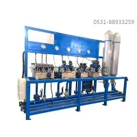
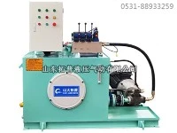
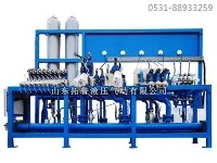
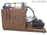
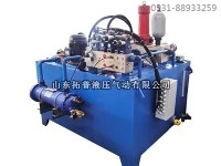
A low-pressure thin-oil station primarily consists of an oil reservoir (with a built-in magnetic mesh filter), low-pressure oil pump units, check valves, a duplex mesh filter, a plate-type cooler (or shell-and-tube cooler), valves, an automatic electric heater, a thermometer, a pressure gauge, a pressure controller, an oil level indicator (sight gauge), and high/low oil level alarms.
(1) Oil Reservoir
Its primary function is oil storage; it also serves to dissipate heat and allow impurities in the oil to settle.
(2) Heater
Heats the oil within the reservoir. When the oil temperature drops below the preset lower limit, the electric heater activates automatically; it stops automatically once the oil reaches the normal operating temperature.
(3) Two Oil Pump Units (Typically)
Commonly used pump types include screw pumps and gear pumps. The station is equipped with two pumps of equal flow rate and pressure capacity: one serves as the primary pump, while the other acts as a standby. During normal operation, running a single pump meets the system's requirements, while the standby pump remains ready for immediate activation.
(4) Duplex Mesh Filter
Located upstream of the cooler (plate-type or shell-and-tube), this filter handles oil flow rates that depend on viscosity: higher viscosity hinders flow, while lower viscosity improves it. Higher temperatures reduce viscosity, thereby improving flow capacity and filtration efficiency; the sequence of filtering before cooling achieves this objective.
(5) Cooler (Plate-type or Shell-and-tube)
Heat generated during continuous equipment operation is absorbed and carried by the lubricating oil. As the oil passes through the cooler, the accumulated heat is transferred to the cooling water, ensuring the oil temperature remains within the range required for equipment operation.
(6) Oil Return Magnetic (Grid) Filter Unit
Installed at the reservoir's oil return inlet, this unit filters out both ferromagnetic and non-ferromagnetic impurities from the oil returning from lubrication points. (7) Safety Valve
The safety valve ensures that the system's maximum operating pressure does not exceed its set value. When the system pressure reaches the set value, the valve opens, allowing part or all of the oil to flow back into the reservoir.
(8) Instruments
These display values such as temperature, pressure, and fluid level at various points in the system, enabling the operator to intuitively monitor the system's operating status.
(9) Control Components and Electrical Control Cabinet
These monitor system parameters such as temperature, pressure, differential pressure, and fluid level. When set values are reached, signals are sent to the electrical control cabinet, which then controls the operation of key system components or triggers audible and visual alarms.
(10) Fluid Level Controller
This monitors and regulates the oil level in the reservoir. When the oil level drops to the minimum allowable limit, the controller triggers a low-level alarm and simultaneously forces the oil pump and main unit to stop. If the oil level rises to the maximum limit (potentially due to the ingress of water or other media), a high-level alarm is triggered; immediate inspection and corrective action are required to resolve the issue.